Chapter 7
Instructor: Baber Sheikh (Visiting Faculty)
Data Flow Architecture views the entire software system as a series of transformations on successive sets of data.
Data moves from one component to the next → each component transforms the data → passes it forward.
Think of a pizza shop where each station does one job:
Dough Station → makes the base → Sauce Station → adds sauce → Topping Station → adds toppings → Oven → bakes it → Boxing → ready!
Each station doesn't care WHO is before or after it. It just takes input, transforms it, and passes output. That's Data Flow Architecture!
Components don't know each other — only input/output matters.
1. Batch Sequential
2. Pipe &
Filter
3. Process Control
Compilers, data processing, multimedia streaming, embedded systems.
| Feature | Batch Sequential | Pipe & Filter | Process Control |
|---|---|---|---|
| How Data Moves | Whole batch at once | Continuous stream (incremental) | Variable updates via feedback loop |
| Concurrency | ❌ None — Step A finishes, then B starts | ✅ High — All filters work simultaneously | ⚡ Real-time continuous loop |
| Control | Explicit (Script drives order) | Implicit (Data drives flow) | Loop (Sensors drive actions) |
| Latency | 🐢 High (wait for full batch) | 🐇 Low (start immediately) | ⚡ Near-zero (real-time) |
| Interactive? | ❌ No user interaction | ❌ No user interaction | ✅ Yes (user sets target) |
| Easy Example | 🏦 Bank: Process ALL salaries → then report | 🚗 Car Wash: Soap → Rinse → Dry (all at once) | ❄️ AC: Measure temp → adjust cooling → repeat |
| Best For | Tape/File processing, Billing | Compilers, Multimedia, Unix CLI | Embedded systems, IoT, Robotics |
| 🎓 One-Liner | "Finish everything, then move." | "Everyone works at the same time." | "Measure, adjust, repeat forever." |
🎓 Crux: Choose Batch for simplicity, Pipes for speed, and Control for physical feedback systems.
One central data store sits in the middle. All software components (called agents) connect to it. Agents never talk to each other directly — everything goes through the data store.
Imagine your class WhatsApp group:
✅ That's Data-Centered Architecture! One shared place, everyone accesses it.
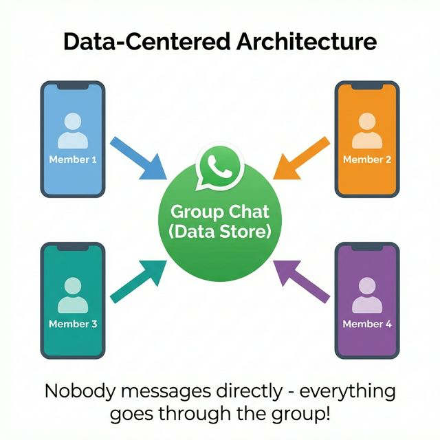
The system has only 2 major parts:
The central hub — stores all shared data. Provides: Insert, Delete, Update, and Retrieve operations.
Think: Database / Shared Folder / Cloud Drive
Software components that work independently. Each reads/writes data to the store without knowing about other agents.
Think: Apps / Modules / Services
Data-centered sub-type 1: "Agents form the Logic"
Data Store = Passive (Lazy) 😴
Agents = Active (Hardworking) 💪
The agents decide when to read/write data. The data store just sits there waiting.
🏪 Like a Library: Books (data) sit quietly on shelves. You walk in, pick a book, return it. The library doesn't chase you!
Data-centered sub-type 2: "Data triggers the Logic"
Data Store = Active (Boss) 🫡
Agents = Passive (Waiting) ⏳
The data store triggers events. When data changes, it notifies agents to wake up & act.
📢 Like a Classroom: Teacher writes on the blackboard → students react to what they see. The board drives the action!
| Feature | Repository | Blackboard |
|---|---|---|
| Control Flow | Agents (User Logic) | Data State (Triggers) |
| Data Store | Passive (Wait for query) | Active (Notify agents) |
| Connection | Explicit Invocation (Call) | Implicit Invocation (Pub/Sub) |
| Agents Role | Active — decide when to access data | Passive — wait for notification |
| Communication | Pull-based (Request/Response) | Push-based (Event-driven) |
| Best For | DBMS, Business Apps, CASE | AI, Speech/Pattern Recognition |
| Data Stability | Stable (defined schema) | Evolving (hypotheses) |
| Analogy | 📚 Library — you go pick a book | 🔔 Alarm — it wakes you up |
Used when data structure is known and stable.
Used when problem is complex and ill-defined.
💡 Rule of Thumb: If data is structured & predictable → Repository. If data is evolving & uncertain → Blackboard.
By the end of this chapter, you should be able to:
Introduce hierarchical software architecture concepts.
Describe Main-Subroutine, Master-Slave, and Layered architectures.
Discuss application domains (OS, Networks, etc.).
Discuss benefits and limitations.
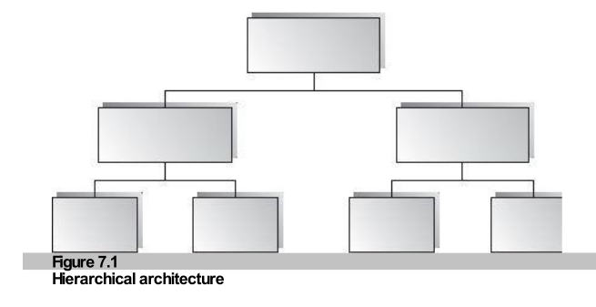
The system is viewed as a hierarchy of logical modules (subsystems) at
different levels.
Dependencies are strict: Lower-level modules
provide services to adjacent Upper-level modules.
Modules connect via Explicit Invocation (Call-and-Return).
#include <stdio.h> then call
printf().
import java.util.* then call
List.add().
System software (OS, Networks) is the classic example.
Changes to a layer only affect its adjacent upper layer (and only if the interface allows it). No ripple effects to the whole system!
Hierarchy is often combined with other styles!
Classic procedural programming. A main controller calls sub-procedures to do specific tasks.
Parallel computing. A master distributes identical work to slaves and collects results.
The "Onion" model. Distinct layers (Presentation, Logic, Data) with strict visibility rules.
Simulation. Software that emulates hardware (e.g., JVM) to provide a portable platform.
Figure 7.1: Block diagram of typical hierarchical software architecture
Dominant for decades. The goal is to reuse subroutines developed independently.
Data is often shared by subroutines at the same level.
"Global variables" are common and accessible by related routines.
Data is encapsulated within individual objects.
Information is protected and hidden from the outside.
System is refined vertically until subroutines are simple enough to have a single independent responsibility.
A "Main" program drives the sequencing of subroutine calls (looping over invocations).
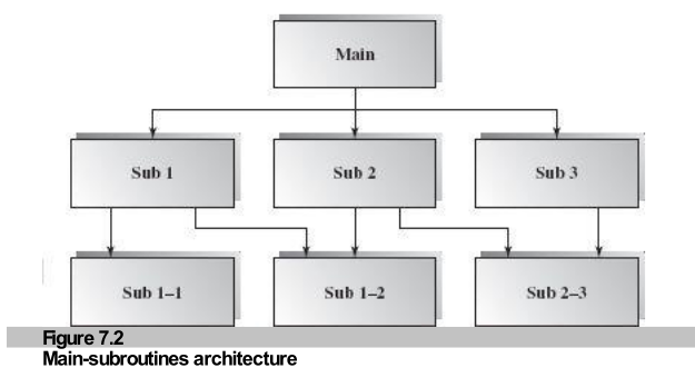
Figure 7.2: Hierarchical Decomposition
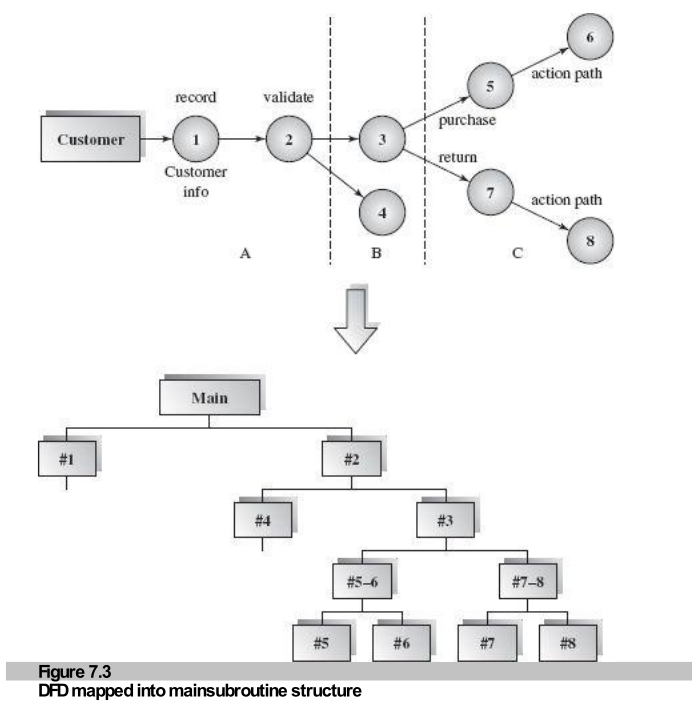
How do we design this? We map a Data Flow Diagram (DFD) to the structure.
Sequential data processing.
Incoming flow is converted into internal format, processed, and shipped out.
Branching logic based on input.
A "Transaction Center" evaluates input and dispatches to the correct action path.
Design Strategy: Identify Transform vs. Transaction centers in the DFD and map them to Main or Sub-controllers.
Figure 7.3: From DFD (Top) to Hierarchy (Bottom)
1. Record Info ➔ 2. Validate Request. Creates the foundation data.
3. Dispatcher evaluates request type: Purchase OR Return.
🏭 Real-World Analogy: A factory manager (Master) assigns identical tasks to assembly line workers (Slaves), then collects finished products.
A variant of functionality where Reliability and Fault Tolerance are critical.
The structure supports parallel execution and redundancy.
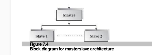
Figure 7.4: Block Diagram
Master configures invocations and processes returned results.
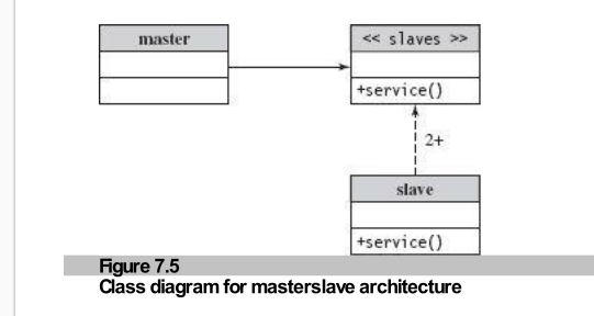
Figure 7.5: Class Diagram
Slaves implement the same
interface (+service()) often in different ways.
service()).
Systems where Reliability is critical:
Failure detection, Time-out mechanisms, and Result Selection (Voting, First-Valid, Average).
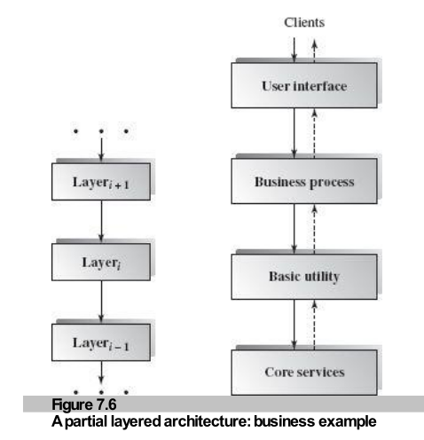
Decomposition into higher (abstract) and lower (specific) layers. Each layer has a sole responsibility.
Layer i+1 invokes services of Layer i via interface.
Request goes Down via method invocation.
Layer i responds to Layer i+1.
Response goes Up via method return.
Pure Layered: Only talks to adjacent layer.
Bridging: Upper layer skips a level down (Performance optimization).
Breaching: Lower layer calls upper layer (Avoid! Causes dependency cycles).
Figure 7.6: Business Application Layers
Layers can be deployed as components (e.g., Java .jar files).
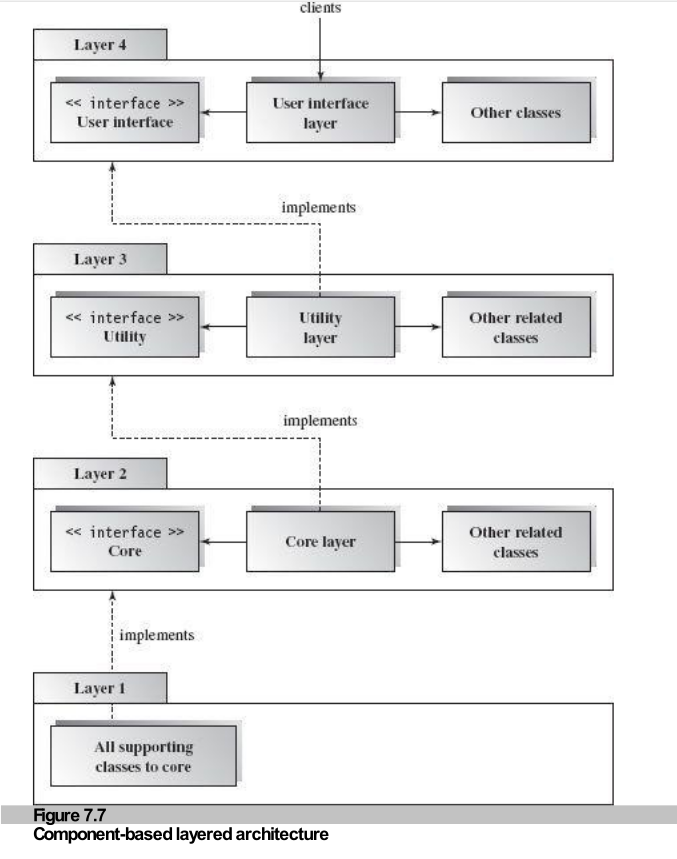
Figure 7.7: Package Organization
Interaction Layer: Handles UI, Validation, Forwarding.
Processing Layer: Logic, Database Access, Calculation.
The diagram shows that the Interaction package depends on the Processing package, but NOT vice-versa. This is critical for maintainability.
This decoupling allows business logic to be independent of the presentation (GUI/Web/Mobile).
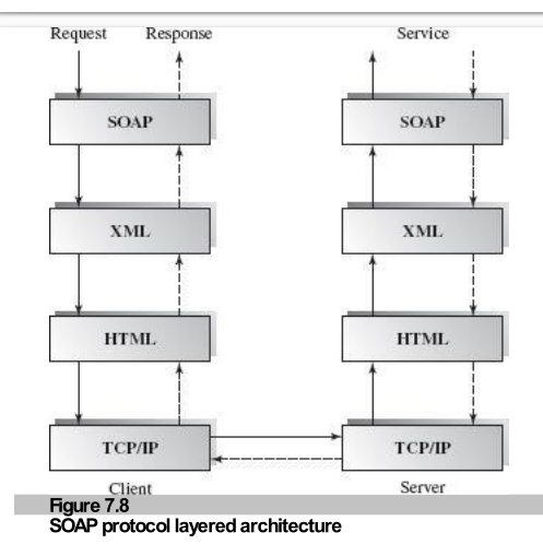
Figure 7.8: Protocol Stack
Data travels Down stack A via TCP/IP, crosses the network, and travels Up stack B to the Server Application.
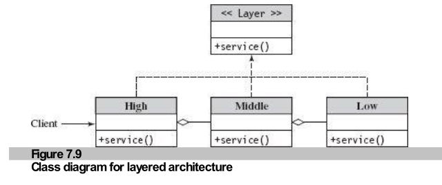
Figure 7.9: Class Interface
All layers implement a common interface (e.g., service()). This allows
upper layers to treat lower layers polymorphically.
"Any problem in computer science can be solved by another layer of indirection."
A Virtual Machine (VM) provides an abstraction that separates the application/language from the execution platform.
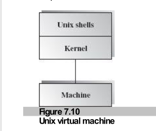
Figure 7.10: Unix Virtual Machine
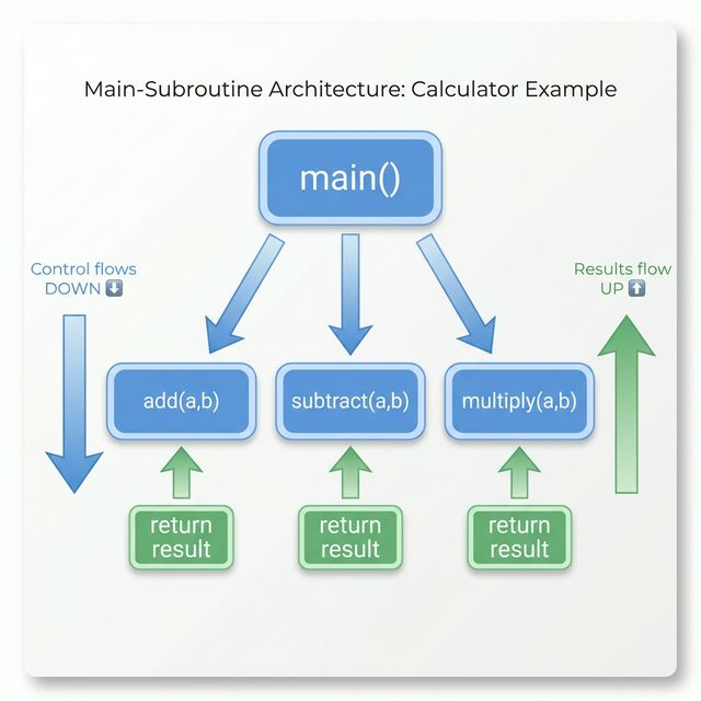
Simple Calculator Example
Unix uses the Kernel as a VM.
Using a VM to unify multiple languages.
The Common Language Runtime (CLR) acts as the VM.
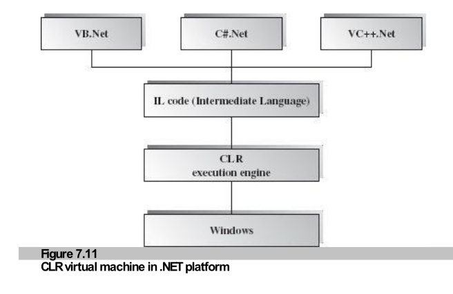
Figure 7.11: .NET CLR Structure
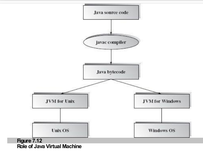
Figure 7.12: JVM Architecture
Java Source ➔ Bytecode (Platform Independent) ➔ JVM (Platform Specific) ➔ OS.
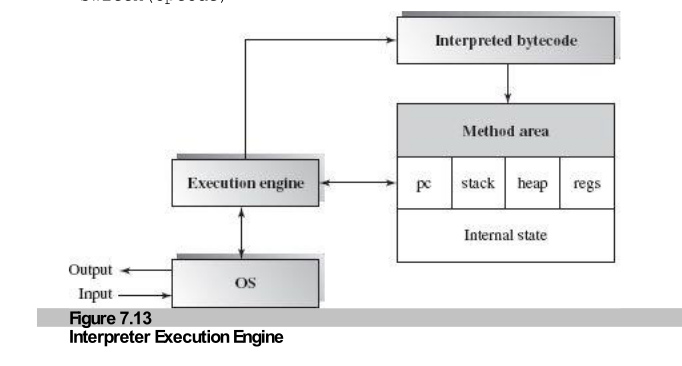
Figure 7.13: Execution Engine
Fetch Bytecode ➔ Fetch Opcode ➔ Execute (Switch case) ➔ Update PC.
The VM acts as a CPU for this bytecode, managing the Program Counter (PC), Stack, and Registers.
Scripting languages (Python, Ruby), Rule-based systems, XML processing, and Cross-platform applications.
The Hierarchical Architecture style decomposes systems into layers where upper layers consume services from lower layers via explicit invocation.
"Structure is the bridge between chaos and order."
| Style | Key Characteristic |
|---|---|
| Main-Subroutine | Functional decomposition, shared data or passing. |
| Master-Slave | Coordination, parallel processing, reliability. |
| Layered | Abstraction layers, request/response, strictly adjacent. |
| Virtual Machine | Platform independence, simulation, translation. |
Hierarchical styles are dominant in system software (OS, Networks) and large-scale applications because they manage complexity through separation of concerns and controlled dependencies.

Questions & Discussion
📚 Chapter 7: Hierarchical Architecture
Main-Subroutine • Master-Slave • Layered • Virtual Machine
💡 "Good architecture is about managing complexity through separation of concerns."